Non-Energizer MEMS Compare

MEMS Driver Technology

Monolithic silicon

why xMEMS has never moved away from it.

3 years in with 3 different generations, yet xMEMS’s speakers are still constructed from pieces of monolithic silicon, requiring an energizer to run properly. That’s not a first-generation compromise waiting to be engineered out; it’s the necessary trade off to achieve sound quality as the top priority. Here’s the acoustic engineering behind that choice, and how it compares to the new coming composite-membrane designs recently entered the market.
Monolithic Silicon

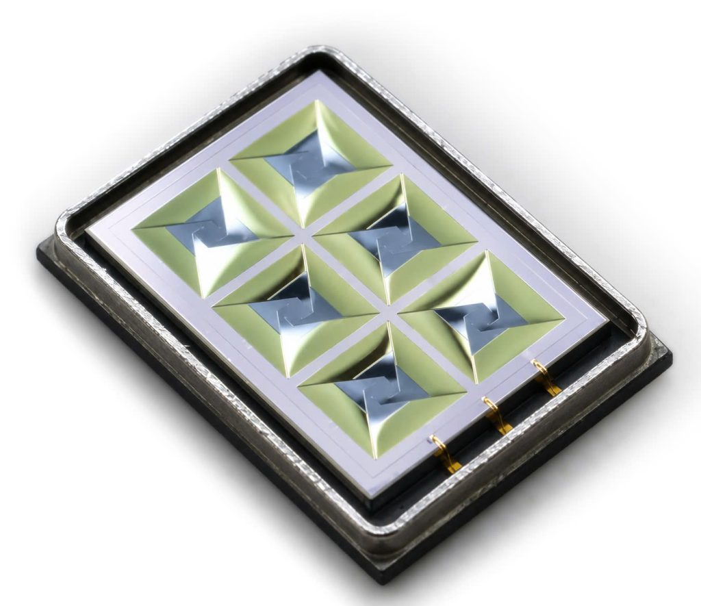
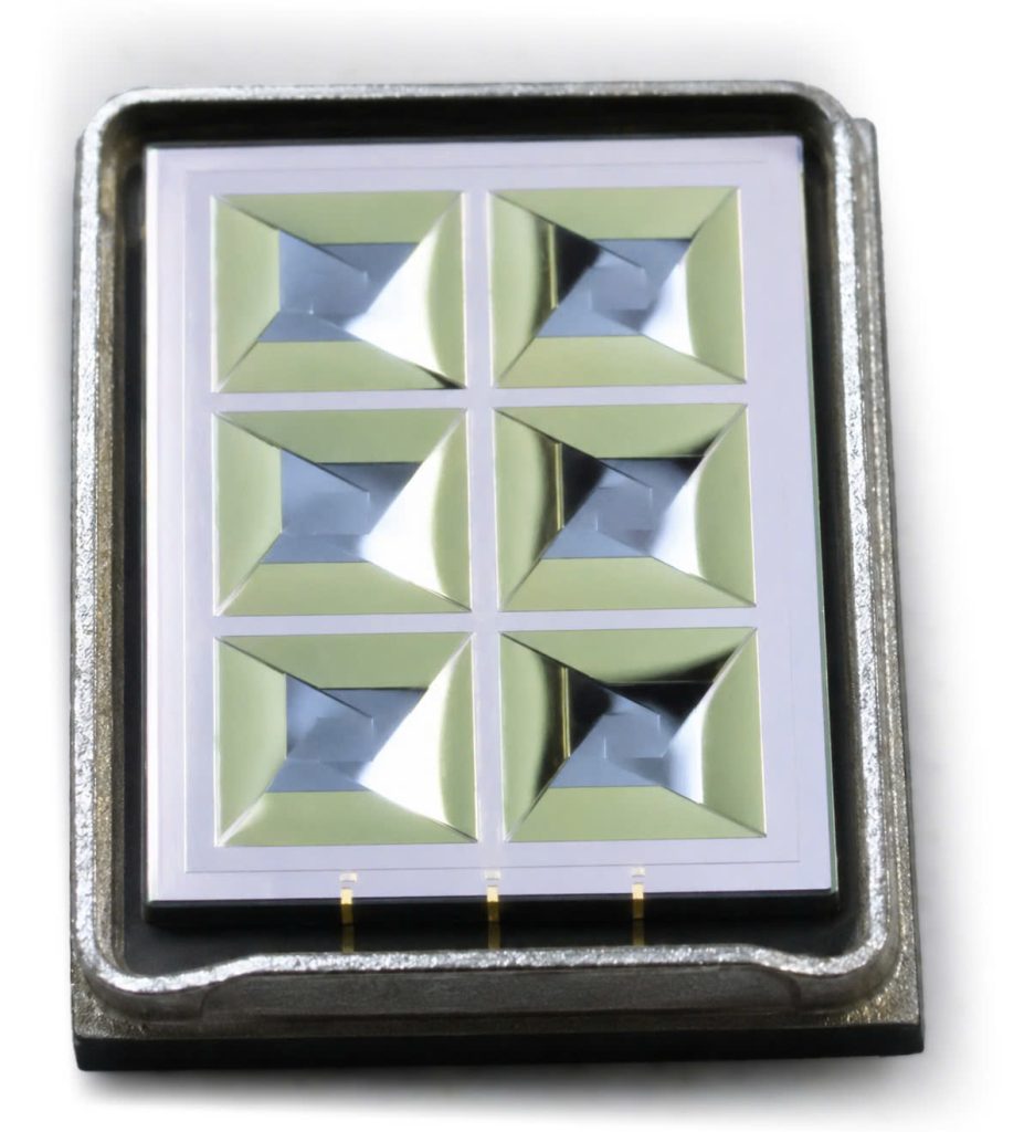
A single crystalline structure — actuator and diaphragm etched from one piece. No seams, no bonded layers.

Rigid · Uniform

Composite Membrane

A softer, layered film bonded onto a support structure — flexible enough to move with less driving voltage.

Compliant · Lower voltage

See it up close

What each diaphragm actually looks like

Monolithic Silicon

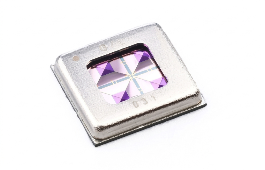
xMEMS monolithic diaphragm — faceted silicon piston array

xMEMS monolithic diaphragm — six-segment variant

Myvox monolithic diaphragm

Composite Membrane (piezoelectric)

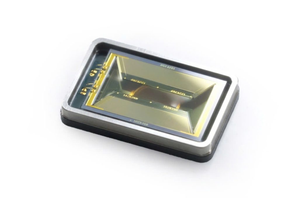
Composite membrane, layered/folded piezo film construction

Electrodynamic Coil MEMS (not piezo)

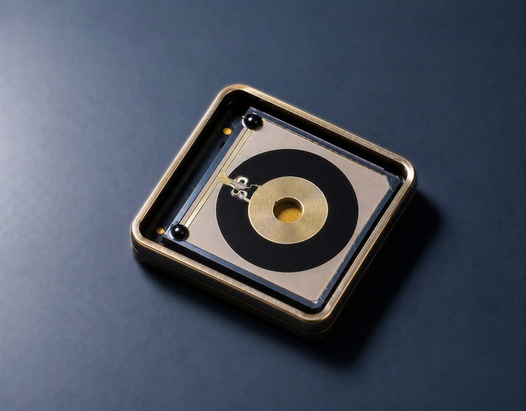
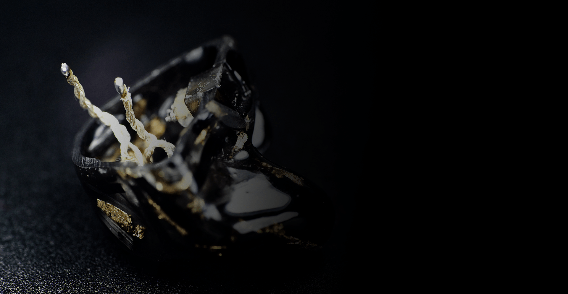
Forte Sound ForteSound™ — MEMS-fabricated coil-and-magnet structure, same principle as a conventional dynamic driver

What’s changed

Why the new MEMS drivers don’t need an energizer

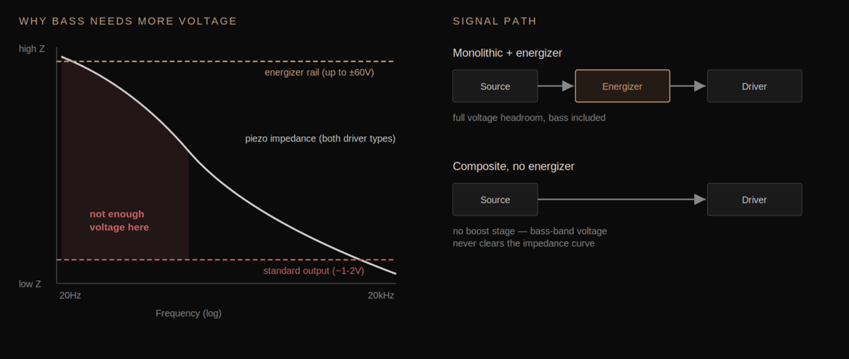
Piezoelectric MEMS speakers move a diaphragm on the principle of piezoelectric by bending it with an electric field — and how much voltage that takes depends heavily on how stiff the diaphragm is. First-generation monolithic silicon designs use a rigid, all-silicon membrane, which is precise but requires a comparatively high bias voltage to bend the silicon — typically driven through a dedicated step-up amplifier with biased outputs, or “energizer,” built into the earphone or source.

Newer MEMS speaker designs replace that throughout silicon membrane with a composite film — often a polymer or hybrid layer bonded to a thinner support structure. Because the material is far less stiff, it deflects more per volt applied. That drop in required drive voltage is what lets these drivers run directly off a phone’s headphone output or a standard IEM cable, with no dedicated amplification stage at all. A genuine and clever engineering shortcut — and it comes at a real acoustic cost.


The electrical picture

Two different shortcuts. Same missing bass.

“No energizer” isn’t one design decision — it covers at least two genuinely different driver types, each skipping the energizer for a different reason, and each paying for it in the bass region a different way.

Composite membrane (piezoelectric) — insufficient voltage

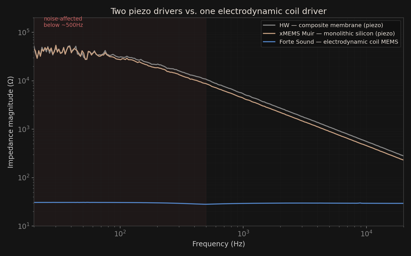
A composite-membrane MEMS driver, like xMEMS’s monolithic silicon part, is a piezoelectric device at its core. Piezo actuators are capacitive by nature, thus their impedance rises steeply as frequency drops — tens of kilohms at 20Hz, down to tens of ohms by 20kHz. To push sufficient charge into a capacitor where its impedance is highest, you need large voltage swing, not current. A standard headphone out can’t develop such large swings across a piezo element’s high low-frequency impedance. Without the energizer, your kick drum never gets the voltage it needs.

Electrodynamic coil MEMS — not enough travel

Not every energizer-less MEMS driver is piezo. Some, like the one in the photo above, which are commonly used in new non-energizer MEMS models lately, are electrodynamic — a MEMS-fabricated voice coil and magnet. This one has the same operating principle as a conventional dynamic driver, just built at chip scale. That’s simply a Dynamic Driver by nature: measured impedance is flat, tens of ohms across the whole band, nothing like a piezoelectric transducer’s capacitive slope. No need of an energizer here, because voltage-headroom is not a problem at all.

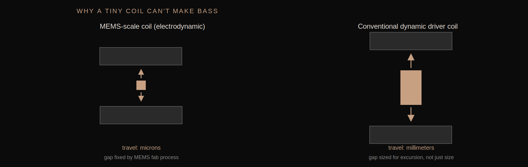
The limit instead is mechanical: reproducing bass means moving large air volume, which means real diaphragm excursion. A coil built at MEMS scale sits in a magnetic gap only tens of microns wide, fixed by the fabrication process itself. No amount of current changes how far it can physically travel.


Two different approaches, same goal – skipping the energizer. However, both driver families land in the same place because of it: neither reaches the bass. xMEMS’s monolithic silicon design is the one on this page’s comparisons that keeps the energizer specifically to avoid that trade.

Measured Impedance — Piezo vs. Electrodynamic

Muir (monolithic) and HW (composite membrane) — both piezo — track the same steep capacitive slope, confirming they share the same underlying electrical behavior despite different diaphragm construction. Forte Sound’s electrodynamic coil MEMS sits flat and low throughout, exactly what a coil-and-magnet load looks like — visual proof it isn’t the same mechanism, and doesn’t have the same fix.

Measured, not assumed

Full-range sound vs. treble-only sound

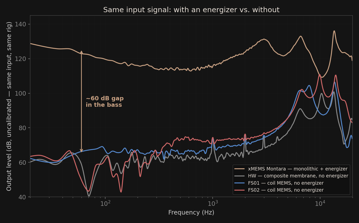
We measured four MEMS drivers on the same rig: an xMEMS Montara (monolithic silicon, piezo, run through its dedicated energizer), one composite-membrane piezo driver (HW), and two electrodynamic coil MEMS drivers (FS01, FS02) — all three of the latter running with no energizer. The energizer also provides gain, so the raw output levels aren’t directly comparable — but each driver’s own balance between bass and treble is. That comparison doesn’t need matched levels, and it’s telling regardless of which mechanism is behind each driver.

Frequency Response — normalized per driver

The monolithic driver stays within about 10dB from 20Hz to 5kHz — genuinely full-range. All three composite drivers fall 20–40dB below their own treble output once you get below 500Hz. Not to mention the massive ~30dB gap above 10kHz compared between having and not having an energizer.

Bass output relative to treble, per driver

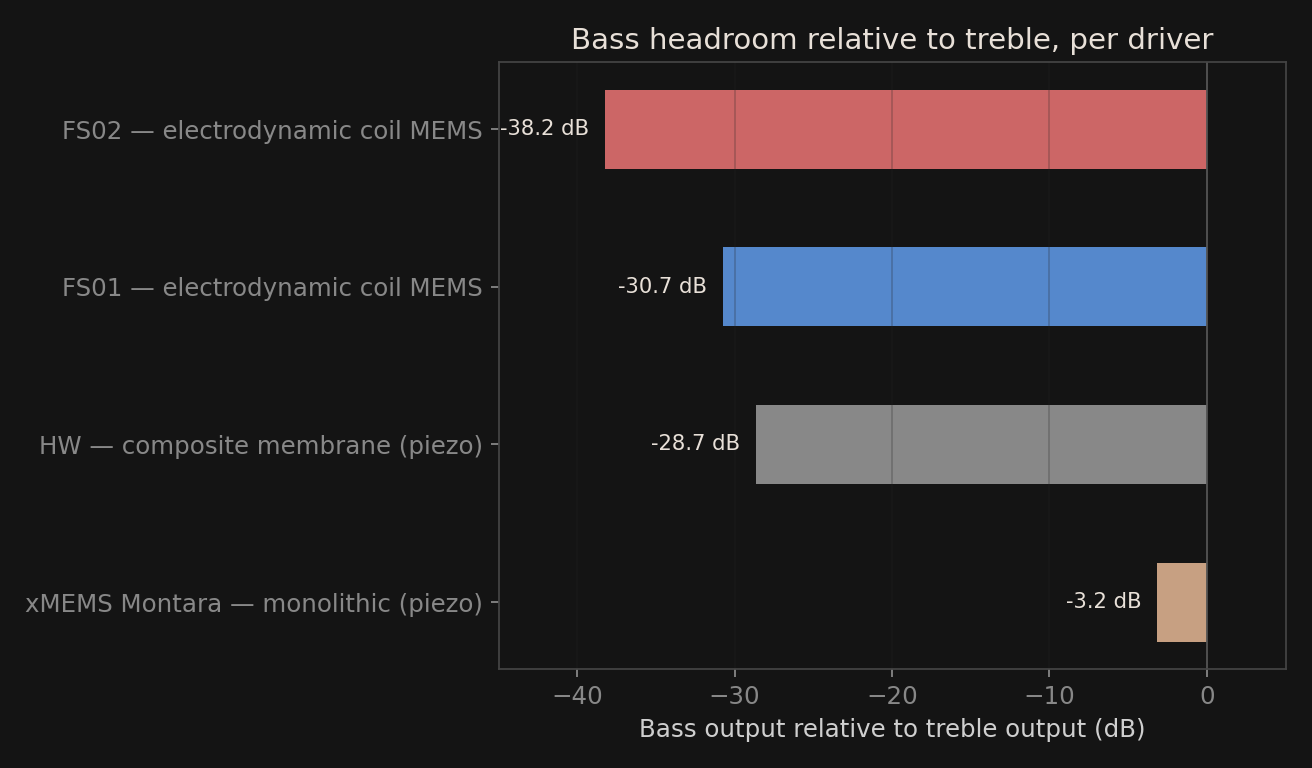
Averaging 20–200Hz against 2–20kHz on each driver’s own curve: the monolithic driver is within 3dB of flat. The composite drivers are 29–38dB down in the bass — a driver that’s 30dB quieter at 100Hz than at 5kHz isn’t reproducing bass, it’s rolling off before it gets there.

Measured with ARTA, 1/24-octave smoothed frequency response, same coupler and rig for all four drivers. Absolute SPL isn’t compared here because of the energizer’s added gain — the composite drivers’ bass rolloff shows up in their own response shape regardless of drive level.

The trade-off

Stiffness isn’t a limitation. It’s the whole advantage.

Monolithic Silicon

e.g. xMEMS-class drivers

  • Breakup-free motion — the whole diaphragm moves as one rigid piston well past 20kHz, instead of flexing unevenly across its surface
  • Very low distortion — no membrane resonances inside the audible band to color the treble
  • Part-to-part consistency — semiconductor-grade fabrication means near-identical L/R matching without hand-tuning
  • Stable across temperature & humidity — silicon doesn’t soften, creep, or absorb moisture like a polymer film can
  • Requires a dedicated bias/energizer stage — the honest cost of the above

Composite Membrane

Passive, no-energizer designs

  • Runs off standard output — no bias voltage or dedicated amp stage needed
  • Softer material — more prone to breakup modes and uneven excursion at higher frequencies
  • Layered construction — bonded interfaces between film and support can vary batch to batch
  • More sensitive to environment — polymer layers can shift behavior with heat, humidity, and age
  • Convenience-first design — optimized to remove the amp requirement, not to maximize fidelity

In practice

What rigidity actually buys you

01

Uniform excursion, not a “best effort” average

A rigid diaphragm moves every point on its surface together, in phase. A compliant membrane bends and flexes non-uniformly as frequency rises — different regions of the diaphragm start moving out of sync, which shows up as smeared transients and a less precise treble.

02

Fewer resonances inside the band you’re listening to

Softer, layered membranes settle into their own mechanical resonances at lower frequencies than a stiff silicon plate does. Push a composite membrane hard enough for real output, and some of that behavior lands inside the audible band instead of safely above it.

03

Fabrication precision you can hear

Monolithic silicon parts come off the same semiconductor process every time — actuator and membrane etched together, not bonded by hand. That translates to L/R channel matching and imaging precision that layered, adhesive-bonded composite structures struggle to match at scale.

04

Long-term stability in an ear canal

An IEM lives somewhere hot, humid, and in constant contact with skin. Silicon’s mechanical properties don’t drift with heat or moisture. Polymer composite films are more vulnerable to exactly that kind of long-term aging — the diaphragm you measure on day one isn’t guaranteed to be the diaphragm you have a year later.

Built around the driver, not around convenience

Soranik’s MEMS-equipped IEMs are engineered with a purpose-built energizer stage from the ground up, so the silicon diaphragm never has to be compromised to fit a simpler circuit.

Explore the Technology